Functional description
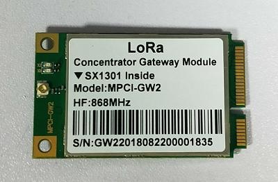
It is a family of LoRa concentrator cards with mini PCIe form factor based on SX1301, which enables an easy integration into an existing routers and others network equipment with Lora Gateway capabilities.
It can be used in any embedded platform offering a free mini-PCIe slot with USB and SPI connectivity.
The card is a complete and cost efficient LoRa gateway solution offering up to 10 programmable parallel demodulation paths. It targeted at smart metering fixed networks and Internet of Things applications with up to 500 nodes per km2 in moderately interfered environment. The modules have the industry standard PCI Express Mini Card form factor, which enables easy integration into an application board and is also ideal for manufacturing of small series.
|
Module
|
Frequency
|
|
Protocol
|
LoRaWAN 1.0.2
|
|
Lora Chipset
|
SX1301
|
|
Dual-Band
|
863-870MHz,915-923MHz
|
|
Frequency Range
|
EU 863-870MHz,US 902-928 MHz,AU 915-928MHz,AS 923MHz, South Korea 920-923MHz
|
|
Power Input
|
DC 3.3 ± 5%
|
|
Hardware Interface
|
Mini-PCIE
|
|
Software Interface
|
USB/SPI
|
|
Multichannel
|
8uplinks、1downlink
|
|
LEDs
|
2*LEDs for PA_EN and LNA_EN
|
|
USB
|
USB2.0, USB-to-SPI bridge FT2232H
|
|
Node Numbers
|
500 nodes/km2
|
|
Range
|
Urban2~4km/Subur5~10km/Open Area>15km
|
|
Power Consumption
|
TX (max): 135 mA
RX(all channels):260mA
Ldle:71mA
|
|
RX Sensitivity
|
Up to -136.5dBm@SF12, BW 125KHz
|
|
Max RF Output
|
Up to +25 dBm
|
|
Mean RF Output
|
Up to +23 dBm
|
|
Operation Temperature
|
-48 to +85° C
|
|
Size
|
50.95 x 30 x 4.5 mm (PCB)
|
1.1.1. Module supply input
The card must be supplied through the 3.3Vaux pins by a DC power supply. The voltage must be stable, because during this operation the current drawn from 3.3Vaux can vary significantly, based on the power consumption profile of the SX1301 chip (see SX1301 DS).
1.1.2. Antenna RF interfaces
The modules have one RF interfaces over a standard U. FL connectors (Hirose U. FL-R-SMT) with a characteristic impedance of 50. The RF port (ANT1) supports both Tx and Rx, providing the antenna interface.
1.1.3. SPI interface
A SPI interface is provided on the PCIe_SCK, PCIe_MISO, PCIe_MOSI, PCIe_CSN pins of the system connector. The SPI interface gives access to the configuration register of SX1301 via a synchronous full-duplex protocol. Only the slave side is implemented.
1.1.4.USB interface
The card can support the high speed USB to SPI by FT2232H, it includes a high-speed USB 2.0 compliant interface with maximum 480 Mb/s data rate, representing the interface for any communication with an external host application processor. The module itself acts as a USB device and can be connected to any USB host equipped with compatible drivers. For more information, please refer to the data sheet of FT2232H.
1.1.5. RESET
The card includes the RESET active-high input signal to reset the radio operations as specified by the SX1301 Specification
1.1.6. SPDT_SEL
The card includes the SPDT_SEL input for selecting SPI or USB interface. SPDT_SEL="H", USB Port Enable, SPDT_SEL="L", SPI Port Enable. Internal Pull UP, Default USB Port.
1.1.7. GPS_PPS
The card includes the GPS_PPS input for received packets time-stamped.


